 +44 1744 734123
 info@plastech-controls.com
 Navigation
Conveyor-fed leak detector available in a 1-4 head configuration.
While still supported, the LT1 has been superceded by the LTU5000. This updates the control system to a new advanced touch-screen design while remaining backwards-compatible with the LT1.
 LT1-2 Twin Channel Leak Detector Mounted on SKF conveyor (An older panel design shown here)
A range of options are available:
- Blocked / Choked Neck Bore Detection
- Fallen bottle detection and rejection
- Infeed brake
A range of options are available:
- Blocked / Choked Neck Bore Detection
- Fallen bottle detection and rejection
- Infeed brake
A range of options are available:
- Blocked / Choked Neck Bore Detection
- Fallen bottle detection and rejection
- Infeed brake
Leak Tester Features
The LT1 series of leak testers have many advanced features:
1.1. High accuracy leakage measurement
The system uses a temperature compensated pressure transducer with a low noise amplifier and high speed, high resolution analog to digital converter. This minimises measurement errors.
1.2. Flexible bottle transport system
Timings can be easily adjusted to optimise bottle transport, where required, without sacrificing test time.
1.3. Microprocessor control system

LT1 Alphanumeric Touch Panel
- Reliable - Hardened against very high levels of mains spikes and static discharges.
- Flexible - can quickly be re-programmed for special needs.
- Future-proof - Large number of spare inputs and outputs to allow future expansion provided at no extra cost.
- Easy to Set - Two line alpha-numeric display allows quick, accurate setting and display of test parameters.
- Easy to Fault Find - Diagnostics are provided from the front panel, allowing engineers to quickly verify every part of the system.
- International - Since all information is presented on the front panel display, it is easy to change the program to use another language (where the system is to be used in a non - English speaking country). 1.4. Modular pneumatic system
Allows quick customisation for special needs.
Allows easy expansion of system to include extra facilities even after installation.
1.5. Cost Effective
The circuit cards have been designed and programmed specifically for this application. Great care has been taken to ensure that the system is easily re-programmable, expandable and reliable. This means that the performance and cost limitations of using a bought-in Programmable Logic Controller are avoided.
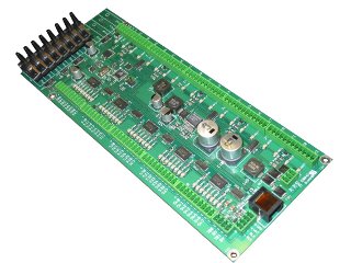 Up to 12 channels of leak detection on a single PCB
 1.6. Options
The leak tester design is highly flexible with respect to software, electronics, pneumatics and mechanics. This allows a wide range of options (see following page) to be added at any time, even after installation.
1.6.1. Choked Bore / Ovality Test
A probe fitted to the test head checks whether the neck is occluded or deformed.
1.6.2. Height Check
A fibre-optic sensor checks that the bottle is not too tall. This can detect folded over base flash on some bottles, as well as neck flash.
1.6.3. Automatic self test
This can be used to periodically check the operation of the leak tester. Every 100 cycles (or any other number), a valve is turned on which introduces a known leakage into the system. A leak test is then performed. If the known leak is not detected, then the system will halt with an alarm.
This technique can reduce the use of “test bottles” to a minimum.
1.6.4. Conveyor halt during test
This is recommended since it improves leak tester accuracy. However, this is not always practical when the leak tester is attached to an existing conveyor system.
1.6.5. Auxiliary Sensors
Spare inputs are available which can be used to connect other sensors which examine the bottle during the leak test. Examples might be label sensors, flash detection sensors or vision systems. The leak tester would fail the bottle if any of these inputs are triggered.

1.6.6. Bottle transport options
A variety of bottle transport options can be fitted to replace the standard method. It is recognised that the standard method may not always be suitable, although we have found that is the most flexible as well as the most cost effective. Other methods include side clamps and holding moulds.
1.6.7. Stabilisat ion Plate
A pneumatically operated mechanism can be fitted to the infeed of the leak tester. This is only required when the conveyor is to be fed directly from the output of a blow moulding machine with violent take-out movements. The queue of bottles is supported by the plate when push-out occurs. The plate then opens, allowing the bottles to travel down the conveyor.
1.6.8. Vacuum Operation
The system usually pressurises the bottles during the leak test. However, it is possible to supply the system for vacuum operation where required.
1.6.9. Special test pressure
The system test pressure is adjustable over a limited range (see specification). If this range is not sufficient, a different transducer can be fitted to allow any test pressure desired.
1.6.10. Data logging / SPC
The standard system maintains counts of passed and failed bottles. More extensive data logging and SPC features can be implemented by exchanging the controller PCB for one with the SPC option fitted.
2. Specification
| Electrical Power Supply | 110/120 or 220/240 VAC single phase |
| Electrical Power consumption | 300 VA maximum |
| Air Supply | 4-10 bar |
| Air Consumption | 1 litre / minute typical |
| Minimum bottle volume | No lower limit |
| Maximum bottle volume | 20 litres (unit will still work with any volume, but cycle time would be |
| improved using another model). | |
| Test Pressure | Adjustable, 5 - 50 mB. This range can easily be changed on request. |
| Cycle Time | 1.0 - 20.0 seconds, adjustable. |
| Hole Size Detected | Dependent on cycle time and container size. (See graph below). For a 500ml |
| bottle and at 20 bottles per minute, the hole detected would be 0.1mm. | |
| Leak Test Method | Pressure Decay, Auto-zero, Auto-Scale. |
| Transducer | Semiconductor strain gauge diaphragm, 0.00 - 65.00 mB, 0.02% resolution, |
| 20 x Overpressure Protection. |
 +44 1744 734123
 info@plastech-controls.com

